Approach Plates
There are many requirements and procedures in IFR flight. The thing a lot of pilots have anxiety about are instrument approaches…with good reason, they’re how you safely return to an airport when you can’t see it.
Let’s break down an approach plate…it’s structure, the information provided, and how to read it. Below is the approach plate for the ILS 30 at KLGB.
I doubt this is your first time looking at one of these, but if it is (or if you’re early in your instrument training) we’ll break down all the elements here.
Each approach plate follows the same structure, starting with…how do we know which approach we’re looking at?
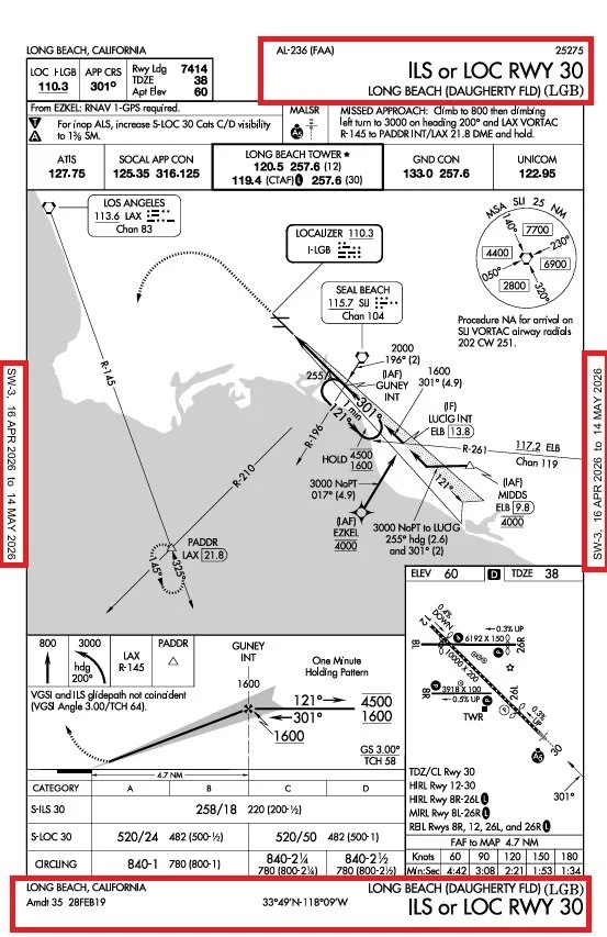
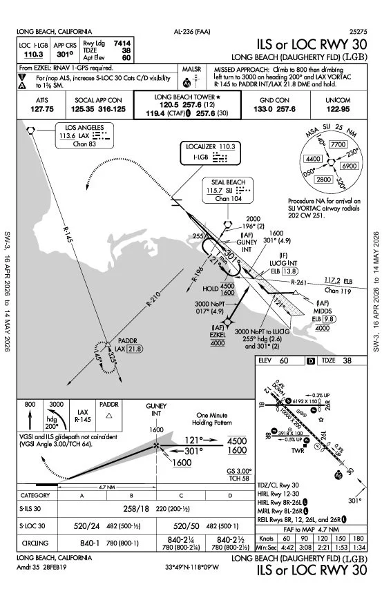
At the top and bottom of each approach plate, you’ll see some basic information (highlighted with a red box above). This will tell you the name of the approach (ILS or LOC RWY 30 in this case), the airport at which this approach is located (LONG BEACH (DAUGHERTY FLD)(LGB)), the FAA document number, and some additional identifying information like amendment date and coordinates. The side margins contain the effective dates of this chart. It’s very important to check this info as you brief the approach. 1. you want to make sure you’re looking at the correct approach and 2. you want to make sure the chart is current.
Now that we know which approach we’re looking at, let’s look at the “meat and potatoes” of the approach.
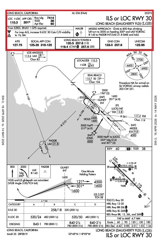
The top section of the approach plate is the Briefing Strip. This section gives you the information you need to set up for the approach.
Starting at the top, the primary ground-based nav-aid frequency will be shown. For this approach, it’s the ILS Localizer Frequency 110.3. Next to that is the Final Approach Course 301°. These two items allow us to set up the approach on our nav radio. To the right of that is the runway landing information, which we should have already briefed during flight planning but it’s provided here again since it’s relevant.
Below that are a Notes Box which will provide relevant notes that may affect how you fly the approach, information concerning the Approach Lighting System (ALS), and textual Missed Approach Instructions. The Missed Approach Procedure is shown in two other locations that we’ll discuss below.
Finally, at the bottom of the briefing strip, all of the relevant Comm Frequencies are listed. This includes the ATIS, approach, tower, and ground frequencies…everything we’ll need to be able to properly communicate on the approach.
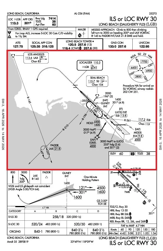
The map section in the center of the approach plate is called the Plan View, or basically the top down view of the approach. This gives us our lateral routing shown with thick black lines, optional routing or cross-radials with thin black lines, all of the fixes/navaids relevant to the approach, and any altitude requirements at each fix. There will be another blog post on how to brief and approach where we’ll learn how to decipher the information presented.
As mentioned previously, the Missed Approach Procedure is also shown on the plan view in the form of dashed lines. It’s important to read any notes in the plan view.
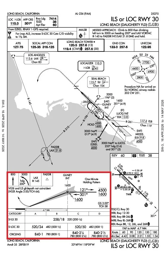
Below the plan view will be a couple items…the one boxed above is the Profile View (basically the side view of the final approach segment) and the Minimums. The profile view will show the vertical flight path for the approach including minimum altitudes at the fixes shown, course information, glide slope information, and distances. You’ll notice that in the top left corner is the missed approach instructions for the 3rd time…this time in graphical form.
The minimums contain both the minimum altitudes like the DA for the ILS or the MDA for the LOC or CIRCLING approach. The numbers also include minimum visibility for the approach. For the ILS category A, the minimums are 258/18, which can be read as 258’ MSL Decision Altitude (your minimum altitude) and 1800’ RVR (or minimum visibility). The Circling minimum of 840-1 can be read as 840’ MSL Minimum Descent Altitude and 1SM required visibility. Again, another post will discuss how to actually use those numbers while flying an approach.
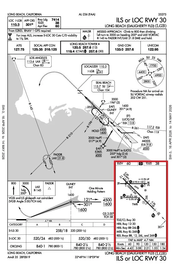
The final section on our approach plate is the airport diagram. Just like looking at the Chart Supplement, This shows us a diagram of the airport including runway information, tower/beacon locations, lighting information, and landing distance information. The top of the diagram also includes field elevation and touchdown zone elevation (TDZE)…very important information as you descend on an approach in low visibility. At the bottom of this section are times based on ground speed. As you can see, these give us the time it will take us to fly from the Final Approach Fix to the Missed Approach Point. For an ILS or a GPS approach, these aren’t relevant except for situational awareness. For a LOC or CIRCLING approach, this will allow us to determine when we’ve reached the MAP without the presence of other information (like DME or GPS).
That is the structure of every FAA Approach Plate. Sometimes, the profile view and airport diagram are swapped and some information may not be provided depending on the type of approach (a GPS approach won’t have a localizer frequency for example), but every approach plate is presented in the same basic format. In a future post, we’ll discuss how to brief an approach using the information presented in the approach. There are many different structures, but I’ll show you the briefing structure I like to use; AICEATM.